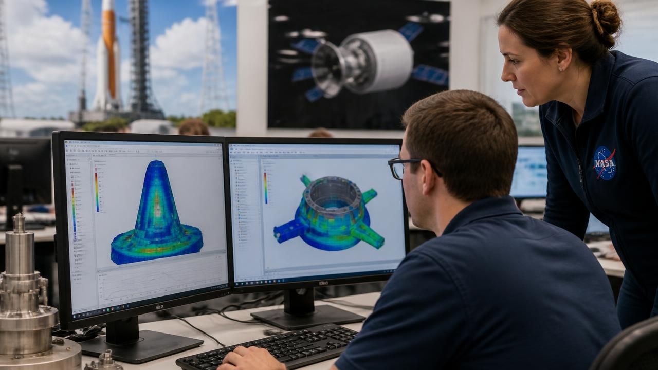
Long before a rocket clears the pad, its fate is being decided inside a computer. NASA engineers in the Dynamic Environments Group of the agency's Launch Services Program Office, based at Kennedy Space Center in Florida, have developed a standardized modeling workflow for finite element analysis intended to make shock and vibration predictions more consistent, more rigorous, and ultimately safer for the spacecraft that ride to orbit.
The work, highlighted by NASA this week, centers on using a commercial digital modeling tool in a new way — not simply as a one-off analysis package for individual missions, but as a repeatable, standardized process that engineers can apply across the variety of hardware the Launch Services Program supports.
Why Vibration Is a Design Driver
The physics behind the effort is unforgiving. Rockets vibrate, shake, and flex intensely as they climb into space, and the forces do not stay neatly confined to the launch vehicle. They propagate through adapters, payload attach fittings, and structural panels into spacecraft packed with delicate scientific instruments, optical systems, and electronics that were designed for the relative calm of vacuum.
Every stage of ascent carries its own signature: the low-frequency rumble of engine ignition and liftoff, the acoustic loading of max-Q, the high-frequency chatter of turbopumps, and the sharp, transient shocks released by separation events and pyrotechnic deployments. Hardware that survives one of those environments can still fail another.
Predicting those loads accurately — and early — is therefore a core part of mission assurance. The Dynamic Environments Group's mandate is to ensure spacecraft and rockets can withstand harsh vibration, shock, stress, or other physical forces before launch, and the new workflow is aimed squarely at strengthening that assurance.
"This computer-based method helps predict how rockets and spacecraft behave under extreme conditions before hardware is built and helps identify weak spots" and potential failure points, the agency said in describing the effort.
That emphasis on the pre-hardware phase is significant. Catching a resonant mode or an under-designed bracket during analysis is orders of magnitude cheaper than discovering it during a vibration test — or, worse, during flight.
A Standardized Workflow, Not Just a Tool
Finite element modeling itself is hardly new; aerospace engineers have used it for decades to divide complex structures into discrete elements and simulate how they respond to loads. What is notable here is the push toward standardization. Different missions, contractors, and payloads have historically arrived with varying modeling conventions, mesh densities, boundary conditions, and assumptions, which makes results difficult to compare and lessons difficult to carry forward.
- Finite element modeling is being applied through a consistent, documented workflow rather than ad hoc per-mission setups.
- The approach is designed to be used on commercial software already available, rather than requiring bespoke in-house code.
- The goal is earlier identification of structural weak spots and better preparation of hardware for the extreme environments of launch and ascent.
- The work is being showcased at Kennedy Space Center, where the Launch Services Program Office coordinates launch vehicle and payload integration.
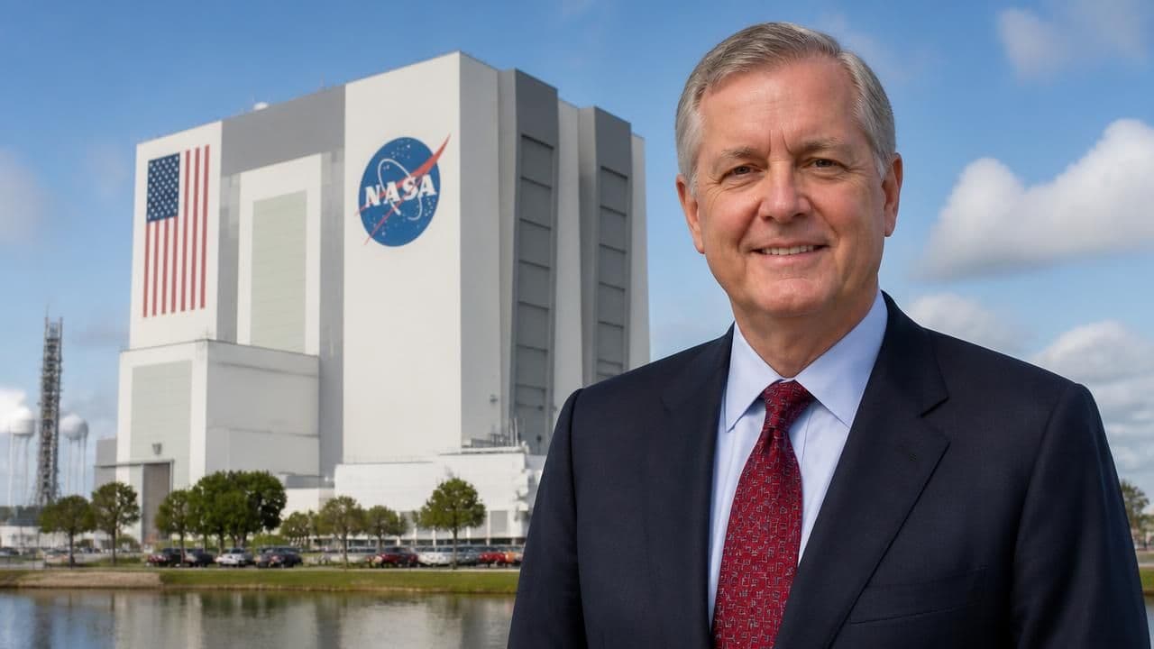
Stirling Allen, a member of the Dynamic Environments Group, presented the commercial digital software at Kennedy Space Center, demonstrating how the tool performs finite element modeling in support of shock and vibration analysis.
A Parallel Track: Materials That Absorb the Hit
Better prediction is only half the problem. The other half is mitigation — designing structures and isolation systems that reduce how much of that energy ever reaches sensitive hardware.
Separate work at NASA's Marshall Space Flight Center in Huntsville, Alabama, has been exploring materials engineered specifically to address that challenge. Reporting has described testing there of so-called MetaSeismic materials, a class of architected metamaterials whose internal geometry is tuned to dissipate or redirect vibration and shock rather than simply resist it passively.
The two efforts are complementary. Modeling tells engineers where the energy goes and which components are most exposed; advanced damping materials and isolators change that path. A standardized analysis workflow makes it easier to evaluate whether a new mitigation technology — a metamaterial insert, a tuned isolator, a redesigned bracket — actually improves the margin on a given spacecraft.
The Bigger Picture
The context here is a launch market that has grown markedly more diverse. NASA's Launch Services Program brokers rides for science missions, technology demonstrators, and international partners on a range of vehicles, from dedicated medium-lift rockets to rideshare opportunities. Each combination of vehicle, adapter, and payload produces a distinct dynamic environment that must be characterized and cleared.
At the same time, spacecraft themselves are becoming more sensitive even as they become more capable: larger deployed optics, thinner solar arrays, and precision instruments all tend to be less tolerant of random vibration and shock than the ruggedized satellite buses of earlier eras.
The engineering payoff of a standardized modeling approach is cumulative. Each analysis informs the next; assumptions become documented institutional knowledge rather than individual expertise. That matters for schedule as much as safety, since analysis cycles sit on the critical path between design freeze and hardware delivery.
NASA has framed the effort in straightforward terms: strengthening mission safety by ensuring hardware is prepared for the extreme environments of launch and ascent. For an agency whose science missions often represent a decade of investment, the value of getting that prediction right before the countdown begins is difficult to overstate.